Tuesday, 27 February 2024

Front "MU" Connector for Planet 2 Locomotive

After receiving some advice and wiring diagrams from Mini Train Systems, I fitted a connector to the front of my Planet 2 locomotive to allow easy connection of the tethered control panel for reverse running.

Front mounted 15-pin connector for the tethered control panel.

Previously, I had been using a 15-pin "VGA" extender cable (Jaycar Part No. WC7500) temporarily running around the outside of the loco for this purpose.  This worked but wasn't very convenient.

The motor controller, inside the loco, actually has a spare 15-pin socket intended for a connection of the control panel at the front, so it was possible to permanently install the existing extender cable inside the loco with the connector emerging through a gap behind the front dummy radiator.  

Running the cable was a bit fiddly, as a had to remove the top from the "engine" compartment, as well as the front battery and some of the screws securing the radiator panel.  To get to the motor controller inside the cab, I also had to remove the cab roof.

I was able to 3D print a mounting bracket for the new connector which clipped onto the top of the front buffer beam so I didn't have to drill any mounting holes in the loco.

While I had the loco in pieces, I replaced the supplied headlight, which was somewhat feeble, with an e-bike headlight the same as I had previously mounted to the roof of the cab for reverse running, and wired both headlights to their respective wires from the motor controller.

The Mini Train Systems controller is quite well thought out, and using the intended method for connecting the control panel at the front meant that the single headlight switch automatically operated either the front or rear headlight, depending on which end of the loco it was plugged into.  Also, when plugged into the front, the sense of the direction switch changes so "forwards" is always away from the driver even through the loco may be running cab first.

And with the control panel plugged in ready to go.

Monday, 26 February 2024

Trial of Point Indicator

As a trial, I made a simple Point Indicator using inexpensive LED lamps available on eBay which are intended as side clearance lights on trucks, trailers, etc.

As a housing, I 3D-printed a new front panel for a plastic "zippy box" including protruding shades over each LED.  For the initial test, the lights change based on the polarity of the 12 V supply to the linear actuator.  Despite only drawing about 5 mA from 12 V, the LEDs are quite bright and visible even in bright sunlight.

To provide an indication when approaching the points in the "trailing" direction, I also mounted a single LED indicator in a low-profile box which mounts next to the left hand rail, and below rail height.

The next stage will be to fit limit switches to the point itself to prove that the blades have moved across completely, and not jammed by a stick or piece of ballast.

Dimensions of the LED lamps

Points set for the main line

Points set for the siding


A more distant view

Thursday, 15 February 2024

First Stage of the Passing Loop

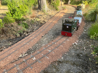
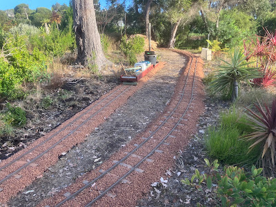
After completing the main line, there were enough track pieces left over to form a siding near the dam.  Another point (right hand) is on order which will eventually be installed where the track runs between the two trees in the background to form a passing loop.

Temporary hook-up of a 12 V battery and linear actuator for controlling the point.  In due course, the battery and solar panel will located in a sunny spot halfway along the passing loop with 12 V power fed to both points via conduits buried in the ballast.

The spacing between the parallel straight tracks is 1.5 m.

After ballasting and installation of a buffer stop, the siding is complete for now.

Some parked wagons to "test" the siding.


Wednesday, 7 February 2024

Completion of the Main Line

Ballasting resumed in the opposite, anti-clockwise, direction from the former end of track near the fruit trees.  The meant a much shorter trip from the ballast pile near the front gate.

Part of this section required extra-deep ballast as the ground is low-lying and boggy in winter.  The width of the weed mat was increased from 600 mm to 800 mm to allow for the extra ballast depth.


By late afternoon and, with a little pushing and shoving, the track was finally joined to form a complete loop without requiring any cutting, which was amazing.  Even though there was still about 10 m which wasn't ballasted, it was possible to drive a train across the gap for the first time at low speed.  

A momentous occasion!


The next day, the last few metres of track were ballasted.


Tuesday, 6 February 2024

Another day, another pipe and more ballast

 Another drain pipe required attention, as it had been pushed out of the ground by roots.  


The pipe weighted down before backfilling and tracklaying.

Meanwhile, another 2 m³ of ballast was delivered, sufficient to do the remaining track with a little bit left over.

At the end of the day, with about 20 m of track to be ballasted, the rails at each end of the loop touched, but with a gap of about 70 mm.  Much thinking that night about how to resolve the gap.

Sunday, 4 February 2024

The longest straight

Ballasting proceeds along the rear of the garden where the longest straight stretch, of about 25 m, is situated.  This section slopes down to the lowest point on the line and includes two level crossing panels for garden maintenance access.

The "top" level crossing in position.

Steady progress down the slope.

An extension required for the overflow pipe from a rainwater tank.

The "bottom" level crossing in position and level.  Later, surplus dirt was used to built up the adjacent grass areas.


Brake Modifications to the New Open Wagons

Both of the new open wagons include electrically-operated parking brakes on one bogie.  Parking brakes are essential as most of the track is...