Saturday, 14 September 2024

Driving Truck to Open Wagon

The first wagon on the railway, the "interim" driving truck, worked fairly well but didn't look realistic. 

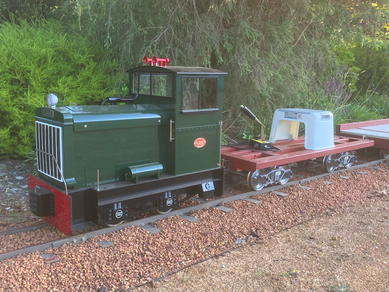
The "interim driving truck" in its original form.

Another problem was that the wood used to make the underframe had a slight twist which meant the whole underframe also had a twist, so that diagonally opposite corners were about 5 mm lower than the other corners.  When constructed, 3 mm packing was inserted at the bogie bearing points to compensate for the twist in the underframe so the wagon would track correctly and not derail.

One option was to build another steel underframe similar to the brake van and re-use the bogies, etc. to make a new open wagon.

In view of the still impending arrival of two open wagons from Mini Train Systems, it was decided to live with the existing underframe and make a new body loosely based on the WAGR GE open wagons.  Conveniently, there are a couple of GE's "preserved" (i.e. rotting away) near the old Denmark station site.

A visit to the local Mitre10 to investigate suitable plywood, resulted in the purchase of 290 x 19 mm pine boards which were a good size for the sides and ends, and easier to handle and cut compared to plywood.  The boards were flat and straight with no twist.

A V-shaped bit in the route quickly made grooves for simulated boards on the sides and ends.


The new wagon body quickly took shape with aluminium angles inside and outside to join the corners, sized to match the angle irons on the original GE wagons.  Packing under opposite corners ensured the body sat level, largely masking the inherent twist in the underframe.

The basic plywood seat can slide back and forth a bit to allow the wagon to be used in either direction.


A timely purchase of a new 3D printer allowed printing of larger parts including cosmetic ribs for the ends of the wagon, based on the dimensions of the prototype's pressed metal ribs.


The handrails and vacuum brake hoses are also 3D-printed.  Further work is still required to design and print ribs and simulated door details for the wagon sides.


Friday, 16 August 2024

Building a Brake Van

The design for a brake van was loosely based on the proportions of the WAGR ZF 4-wheel brake van but adapted to suit the available DNC bogies.  The length of 1150 mm was dictated by the length of the storage track in the garage and the impending arrival of two bogie open wagons from Mini Train Systems.

The welded underframe is made up from 30x30 and 40x40 square steel sections.  The use of 30x30 for the side members matched the proportions of the ZF's 4-wheel underframe, but it complicated the design by requiring tapered ends on the 40x40 cross members.  All good practice at fabrication.


The bodywork at this stage is basically a mock-up made from leftover MDF board.  The eventual plan is to build a more detailed body resembling the WAGR brake van.

Testing the seating position

Handbrake lever connected via cable and pulleys to one bogie

It was decided to press the brake van into service with the temporary bodywork, so it received a couple of coats of Manor Red paint, as well as some metal and 3D-printed details to give some character, as well as working lights at both ends powered from a small LiPo battery.

The brake van has proved to be a useful addition to the railway.  It is quite comfortable to ride in and easy to get in and out of.  In the future, it might be possible to devise a sliding door to disguise the large opening in the side.


Friday, 7 June 2024

Learning to Weld - Building a Low-Floor Wagon

This project started life as a way to learn to weld, using 25 x 25 mm square steel tube salvaged from a pallet on which a ride-on mower was delivered.  After a few practice welds, I realised there was enough square tube to fabricate a low-floor wagon which would be useful for various duties.

The welder - gasless, flux core variety.

The first step was to fabricate one sideframe, and test the strength of the welds by supporting each end on a brick and standing on the middle.  It passed.


After the success with the first sideframe, I ordered a basic welding table which would greatly assist in aligning the overall frame straight and level.

The wagon frame taking shape on the welding table

Within a relatively short time-frame, a rolling wagon emerged from the workshop.  The low level floor is a piece of chipboard which rests on conveniently located lugs which were already attached to the side pieces.  

Short lengths of 25 x 50 mm rectangular tube, left behind by the previous owner of the house, provided attachment points for the bogie pivots and couplers.


I purchased flat bar from the local hardware store to fill in the end parts of the frame.


Welded areas received a good clean-up and a coat of anti-rust primer, followed by an all-over application of Colorbond Manor Red - the railway's standard wagon colour.


The low-floor wagon is routinely used to transport the lawnmower (normal size, not ride-on) and other garden tools to far flung parts of the garden, and also the carry the wheelie bin to the front gate. 

Friday, 3 May 2024

Tracklaying in the Passing Loop

Although it will still be a while before the right hand point to complete the passing loop will arrive, I thought it worthwhile to set out the final track alignment.  One reason was to make sure I don't need to order any additional track pieces.  Also, I wanted to tidy up the remaining ballast in the ballast pile, so it made sense to move some of the ballast to where it would be needed anyway.

I used some spare curved pieces laid on top of the existing track where the point will go, to set out the curve to link up with the existing straight portion of the passing loop, then removed the track pieces and laid weed mat along the alignment.

Weed mat down ready for an initial layer of ballast.

After mulling things over for a week or so, I decided to bite the bullet and remove the 3 m straight track where the right-hand point will go, and replace it with spare 10 m radius curves to mimic the geometry of the future point.  

Spare curved track now leading into the passing loop.

The straight portion of the passing loop has now been extended using the 3 m straight track removed from the future point location, but there is a gap of about 300 mm remaining to join up the passing loop track.


To fill the gap, I cut the end portion from another spare piece of curved track, and drilled new holes for the bolted track joiners.  The slight additional curvature, about 1.75°, pretty much corrected a slight angular misalignment where the curved and straight tracks meet.  


The buffer stop which was removed from the former end of track has been reinstalled just ahead of the loco in the photo below, on the main track. All that remains in the short term is to level and fully ballast the new track.

The plan now is for the passing loop track to remain as the through track until the new point arrives.  


Sunday, 31 March 2024

Driver's Eye View

This first video was filmed with the camera mounted in the cab of the Planet 2 locomotive, to give a true "Driver's Eye" view.  The train was travelling in an anti-clockwise direction around the main line loop.


This video was filmed in the clockwise direction, with the camera mounted on the cab roof of the Planet 2 locomotive.


Friday, 1 March 2024

"Golden Spike" Ceremony

On Friday 1 March 2024, we had an informal "Golden Spike" ceremony to mark the completion of the main line, witnessed by friends Tricia and Richard who were visiting at the time.

The "Golden Spikes" were actually M6 high tensile bolts which had been spray-painted gold for the occasion, and were installed in place of four regular bolts at the final track join.

Unlike the actual Golden Spikes which were used at completion of historic railways, the gold-painted bolts can remain in position with no risk of being stolen.  Most of the real Golden Spikes end up in a museum after the official ceremony.


Tuesday, 27 February 2024

Front "MU" Connector for Planet 2 Locomotive

After receiving some advice and wiring diagrams from Mini Train Systems, I fitted a connector to the front of my Planet 2 locomotive to allow easy connection of the tethered control panel for reverse running.

Front mounted 15-pin connector for the tethered control panel.

Previously, I had been using a 15-pin "VGA" extender cable (Jaycar Part No. WC7500) temporarily running around the outside of the loco for this purpose.  This worked but wasn't very convenient.

The motor controller, inside the loco, actually has a spare 15-pin socket intended for a connection of the control panel at the front, so it was possible to permanently install the existing extender cable inside the loco with the connector emerging through a gap behind the front dummy radiator.  

Running the cable was a bit fiddly, as a had to remove the top from the "engine" compartment, as well as the front battery and some of the screws securing the radiator panel.  To get to the motor controller inside the cab, I also had to remove the cab roof.

I was able to 3D print a mounting bracket for the new connector which clipped onto the top of the front buffer beam so I didn't have to drill any mounting holes in the loco.

While I had the loco in pieces, I replaced the supplied headlight, which was somewhat feeble, with an e-bike headlight the same as I had previously mounted to the roof of the cab for reverse running, and wired both headlights to their respective wires from the motor controller.

The Mini Train Systems controller is quite well thought out, and using the intended method for connecting the control panel at the front meant that the single headlight switch automatically operated either the front or rear headlight, depending on which end of the loco it was plugged into.  Also, when plugged into the front, the sense of the direction switch changes so "forwards" is always away from the driver even through the loco may be running cab first.

And with the control panel plugged in ready to go.

Accucraft GP40 Wheel Modifications

One issue that I became aware of some time after placing the order for the GP40 was the difference in wheel standards for 7¼" gauge in ...