Thursday, 14 May 2026

Push-Button Remote Control for GP40 Loco

Since I installed the Sabertooth 2x32 motor driver module in my Accucraft GP40, I have been thinking about the option of using a model aircraft style RC unit. However, investigations into the available RC systems revealed complications of using a joystick style controller for forward/reverse control, lights and horn.
Some people on YouTube have used car-type RC units which had a trigger control for speed and forward/reverse, but these seemed more suited to rapid changes of speed and direction rather than smooth control of a train.
I was mainly thinking of using the remote control mode for shunting to avoid getting on and off the train for uncoupling/coupling. It will also allow the loco to be easily driven “light engine” without a driving wagon attached, such as for running around a train.
Then, I hit on the idea of using a push-button remote control similar to what I have been using for points. These use relays which can be programmed for momentary or latched operation, latched being best for points control.

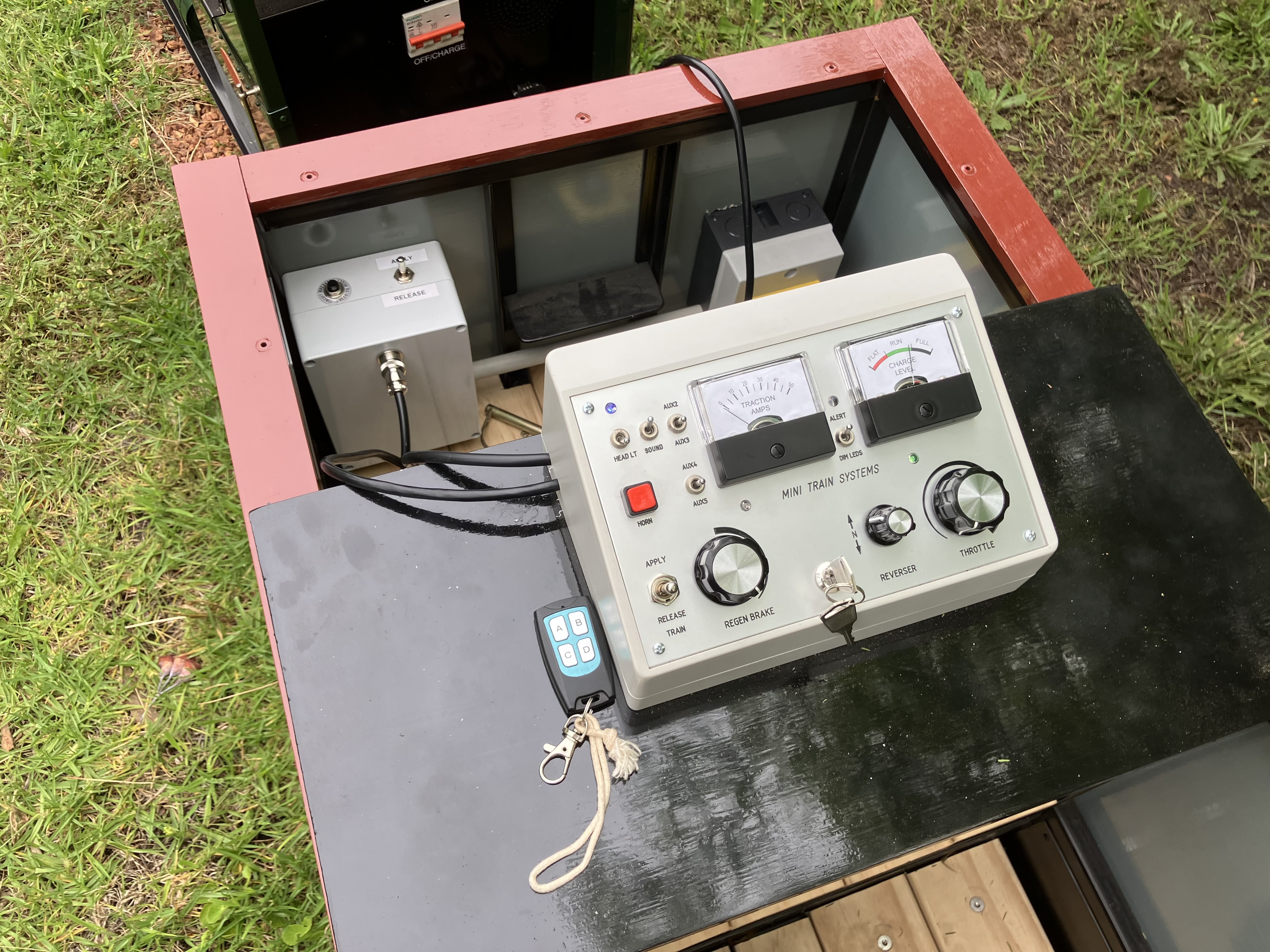
Typical 4-channel Remote Control from eBay

By using the momentary mode, I could assign the 4 buttons for speed increase and decrease, forward/reverse (toggle) and horn. Using a Picaxe microcontroller, I programmed appropriate actions for each of the push buttons, included a degree of “inertia” to avoid sudden movements. The microcontroller outputs a 0-5 V speed control signal, as well as 12 V on/off outputs for forward, reverse, and horn. The electrical interface is compatible with the Mini Train Systems control panel, even though that is not required when using the push button system.
Over the last 2 days, I have made a “proof of concept” model which I was able to test this morning, and it works quite well. Some features include:
  • Button A operates the horn
  • Buttons and B and D increase and decrease speed with 16 steps.
  • Button C toggles between forward and reverse. A short horn toot confirms forwards, two toots for reverse. The forward/reverse control is disabled unless the loco is stopped.
  • There is a deadman timer which brings the train slowly to a stop after about 30 seconds of no button activity. Button C can be used to reset the timer if desired when the train is in motion.
  • Configurable speed limit, currently set to 50% of max speed.
I have a 6-button remote control on order (about $50 on eBay). I plan to use the extra buttons for a rapid (emergency) stop and headlight.
I made a video of testing this morning. When the loco stops at 1:50 in the video, that is due to the deadman timer as no buttons have been activated for approx. 30 seconds.


In the photo below, the remote control receiver (with 4 relays) is on the right and the Picaxe microcontroller is on the left with stacked prototype board on top. The 15-pin connector and cable on the left connect to the loco's MU socket, and supply 12 V DC power to the Picaxe and receiver modules.


Wednesday, 7 January 2026

Installing Sabertooth 2x32 Motor Controller in GP40 Loco

This afternoon's activity was installing a new electronic motor controller in my Accucraft GP40 locomotive for 7 1/4” gauge.

Although the supplied Mini Train Systems motor controller works well in the Planet 2 loco, the two identical units installed in the GP40 have given problems. Lately, one or both controllers (there is one for each bogie) have been cutting out during regenerative braking, leading to reduced or zero braking effect.

To their credit, Mini Train Systems did suggest some changes to try to fix the problem and even sent a spare motor controller for me to try. However, the problems persisted.

The new controller is a Sabertooth 2x32 which is a general purpose motor controller widely used in wheeled robots, model tanks, etc. It can control two DC motors up to 32 amps each, continuous rating.
As it has 2 channels, the one Sabertooth will drive both bogies.

The Sabertooth 2x32 Motor Controller (circled in red)
The box to the left of the Sabertooth in the photo is an interface which I made so I can continue to use the tethered control panel supplied by Mini Train Systems. It provides a 0-5 volt speed signal and a forward/reverse control to the Sabertooth, as well as switching the lights and horn via relays already installed in the loco. The interface also drives the current and voltage meters on the control panel.

Mini Train Systems tethered control panel
The two black cables plugged into the interface unit are from the MU sockets at each end of the locomotive, where the tethered control panel plugs in. As before, the loco direction control is reversed and the appropriate headlight is selected depending on which end of the loco has the control panel plugged in.
The main difference with the Sabertooth is that the separate control for regenerative (Regen) braking no longer functions, and regenerative braking kicks in automatically when the speed control is reduced.
It is not quite as much fun to drive as the ability to shut off the throttle and coast then apply braking as required is no longer available, but it will be easier for novice drivers to manage, and the regenerative braking works reliably, which is useful.
I will investigate adding some electronics to mimic the former coast and brake feature for experienced drivers.
The Sabertooth also has inbuilt "cruise control" in that it maintains a fairly constant speed, applying extra power or regenerative braking as required. On an uphill grade, you can see the current increase. On a downgrade of about 2%, you can see the current drop to zero and the voltage increase slightly as braking energy is fed back into the battery.
Here is a link to the Sabertooth 2x32.
I ordered my Sabertooth direct from Dimension Engineering in the US as the local supplier, Robot Gear (in Perth), was out of stock. However, the delivery from the US took a long time due to the slowness of the US Postal system and it was several weeks before I received notification that it was even ready to leave the US. In the meantime, Robot Gear emailed me to say that new stock has arrived, so I ordered a second unit, which is the one I actually installed. Being a critical item, there was no harm in having a spare available when the other one arrives. From the Robot Gear, the cost was $256 plus local postage.

Monday, 1 September 2025

Accucraft GP40 Wheel Modifications

One issue that I became aware of some time after placing the order for the GP40 was the difference in wheel standards for 7¼" gauge in the US compared to Australia.  The common US profile is defined by the International Brotherhood of Live Steamers (IBLS).  The corresponding organisation in Australia is the Australian Association of Live Steamers (AALS).  The area of concern was the wheel check gauge, which affects how the wheels interact with the frog and check rails when negotiating points (turnouts).  Despite the common 7¼" track gauge, the IBLS wheel check gauge was 3.5 mm wider.  

Prior to installing the electronics and batteries in the GP40, I did a couple of test runs around the railway being pushed by the Planet 2 locomotive.  As I had feared, the loco did not run smoothly through the curved, diverging, leg of points as the wheel flange hit the tip of the point frog, rather than being guided clear by the opposing wheel and check rail.  I only tested at very low speed, but there was a very noticeable bump at the point frog.

A friend in Perth, Richard Stuart, who has a fully-equipped workshop for building miniature trains had previously offered to help if any modifications to the wheels were required, so I removed the bogies from the GP40 and took them to Perth on the next visit.

Underneath view of Accucraft GP40 bogie

The bogies were designed to be convertible between 7 1/4” and 7 1/2” gauge, the wheels being held in place by circlips in axle grooves, with round ended feather keys to prevent the wheels from rotating on the axles.  As supplied, each end of each axle has 2 sets of grooves, offset by 1/8” (3.2 mm), to allow for the gauge change.

An axle in the lathe, ready to cut a new groove for a circlip. 
The red arrow indicates the cutting tool.

As there was no spare space on the side with the drive chain, the solution was to remove each axle and machine a new circlip groove, displaced by 3.5 mm on the non-drive side.  Each axle was then offset by 1.75 mm from its original position, to re-centre the wheels.  The axles are retained in their position by grub screws on the bearing hubs.  

The arrow indicates the 3.5 mm gap between the outside
of the wheel hub and the innermost circlip groove.

Arrows indicate washers inserted between the motor mounts and motors,
to move the motors inwards to maintain chain alignment.

Also, the motors were moved inwards by adding washers to their mounting bolts, to maintain clearance between the chain and the back of the wheel.

New 3.5 mm thick spacer secures the wheel in its new position. 
The notch in the spacer is necessary to allow for the end of the feather key.

Finally, Richard machined 3.5 mm thick spacers to go between the outside of the adjusted wheels and the outer circlips.  It wasn’t feasible to machine a new groove for the outer circlip as the end of the key protruded beyond the face of the wheel hub, which would have interfered with the circlip.  The new spacers required a notch to accommodate the end of the key.

Coupler Height Adjustment


The IBLS standards also differ from AALS standards with respect to coupler height, with the IBLS height being approx. 15 mm lower than AALS.  

The GP40 was supplied with Accucraft knuckle couplers  which are already in use on some wagons, and which are compatible with the Tom Bee couplers which are also in use but currently unavailable.

For interim running, I had modified a Tom Bee coupler to provide a 16 mm downwards offset to better match the GP40 coupler height.

When refitting the bogies to the GP40, I added 12 mm pine wood spacers between the bogie mounts and underframe to lift the overall loco height thus raising the coupler height to match other rollingstock.


Sunday, 17 August 2025

Accucraft GP40 Electronics and Wiring

Although Accucraft can supply the GP40 loco with their own control system, I opted to install the Mini Train Systems PS7 control system so it would match the Planet 2 loco.

I already had a set of 4 batteries, 12 V 75 Ah sealed lead acid type, which had previously been used in a ride-on mower.  Although the batteries were somewhat degraded to about 50% of their original capacity, the remaining capacity should be ample for locomotive use, as the maximum power required is around half that of the ride-on mower, and only for shorter intervals. 

Each pair of batteries is wired in parallel to give 12 V, and the main circuit breaker connects both pairs in series to provide 24 V for the power controllers.  When connected to the battery charger, all four batteries are connected in parallel and charged at 12 V.  The four batteries occupy most of the long hood portion of the loco.

I intended to mount the main circuit breaker inside the cab of the loco where it could be operated through the open side window, but the window opening was too small to get a hand inside.  Instead I mounted the main circuit breaker in the low short hood, which has an removeable top for easy access.

Main circuit breaker mounted in the low short hood.

Due to the GP40's power requirements (1400 W @ 24 V), it needed separate power controllers for each bogie, which are effectively connected the same as two locomotives in multiple unit (MU) operation.

The loco included an aluminium tray for the various electronic bits in the top of the long hood, at the rear.  The major items of equipment are the two motor controllers, circuit breakers for both 24 V and 12 V circuits, and a number of relays for auxiliary items including lights and horn.

Two relays also function as a safety interlock and are controlled via a cable plugged into the first wagon of the train to shut off motor power if the couplings become separated for any reason this preventing a runaway locomotive.

The main "electronics tray"

The motors used on the Accucraft bogies (two motors per bogie) also include an electromagnetic brake.  This brake defaults to the ON position and requires continuous 12 V power to release the brake.  Although useful as a parking brake, the magnetic brakes engage very suddenly and can only be used when the loco is at a standstill.

I wired the brake circuit independently of the safety interlock and 12 V/24V circuit breakers with a separate fuse, so that the brakes would not engage suddenly if the loco became separated from the train.  In that event, it would be preferable for the loco to coast gently to a stop rather than having the brakes suddenly lock up.

I completed the basic wiring and battery installation relatively quickly so that the loco was able to run under its own power 48 hours after delivery.  Although I expected to have to do more of the wiring myself, Accucraft had provided and labelled long enough cables for the motors, brakes, front and rear lights, horns and speakers for on-board sound effects, if desired.

Wiring in progress.  Two of the batteries are visible near the centre of the loco.

The tethered control panel from Mini Train Systems connects via a 15-pin connector, the same type as used for VGA computer monitors.  A later stage of the wiring is to fit these connectors to the headstocks at each end, so that the control panel can be plugged in to operate in either direction.  This work is still in progress.  For the initial testing, the cable for the control panel was routed via the open cab window, as this was the only opening available when the roof panels were in position.

Friday, 15 August 2025

Accucraft GP40 Loco Arrival

A very exciting day for the railway with arrival of an Accucraft GP40 locomotive which had been on order since January 2025.

Towards the end of 2024, I had been thinking about building or buying a larger locomotive, which would be able to handle the grades of up to 3% on the railway.  After exploring some ideas of building a loco using commercially available drive bogies, I decided that the Accucraft GP40 locomotive would be a good option, as I preferred a nicely-detailed loco based on an actual prototype rather than a freelanced design.

The initial inspiration came from a YouTube video of a US miniature railway with a loco in the Florida East Coast Railway livery, as the red-orange, yellow and black reminded me of the 1970's experimental International Orange livery applied to a couple of then WAGR (Western Australian Government Railways) standard gauge locos, including L Class L257.  

Although there are significant differences between the US GP40 loco and the L class, the overall shape is similar including the low "nose" on the short hood.  In the mid 1970's, when this livery was current, I was inspired to hand paint a Bachmann GP40 loco to act as a "good-enough" L class for my HO scale model railway.

L257 "International Orange" Livery - WAGR 1974 Publicity Photo from Rail Heritage WA

When I first enquired with Accucraft, they advised that the loco was made in Japan, but shipped to China for custom painting, and that I would have to arrange shipping from China to Australia.  Fortunately, an online search revealed a company - Shipping Solutions - which was able to handle all aspects of the importation, by sea container, including customs and GST payment.  Once I had confirmed that the import process was manageable, I paid an initial deposit to Accucraft to secure the order.  

A friend was able to source an original WAGR drawing showing the details of the paint scheme, and I prepared a drawing showing the livery overlaid onto an outline drawing of the GP40 locomotive.  I bought 1 litre tins of painted tinted to the appropriate Australian Standard colours for International Orange and Golden Yellow, which I used to prepare colour samples which I posted to the factory address in China.

Accucraft initially estimated that the finished loco would be ready to ship from China in May, but that proved optimistic, partly due to the US tariff situation which meant that other locos being prepared for US customers took precedence to beat the tariff deadline.

One issue that I became aware of some time after placing the order was the difference in wheel standards for 7¼" gauge in the US compared to Australia.  The common US profile is defined by the International Brotherhood of Live Steamers (IBLS).  The corresponding organisation in Australia is the Australian Association of Live Steamers (AALS).  The area of concern was the wheel check gauge, which affects how the wheels interact with the frog and check rails when negotiating points (turnouts).  Despite the common 7¼" track gauge, the IBLS wheel check gauge was 3.5 mm wider.  

Accucraft offered a choice of the IBLS wheel profile or an alternative RMI-25 profile which has a slightly deeper flange which more taper on the front of the flange.  I elected for the RMI-25 flange profile, hoping that the more tapered flange would help when running through points.  Although I was confident the US wheel profile would run ok on normal (plain) track, I was expecting that negotiating the curved, diverging leg though points could be a problem, which turned out to be the case.  

Around the end of June 2025, Accucraft advised that the loco was ready to be shipped from China and the previously arranged shipping plan swung into action, after I had paid a 50% deposit for the shipping component.  The crated loco was loaded into a shipping container with other small LCL (Less than Container Load) freight, and on a ship bound for Fremantle.  

A few days after arrival, the container was transferred to a freight depot in Welshpool, WA, where it was to be unloaded ready for pickup and final delivery.  This proved to be a complication as the freight depot had a slot booking system for freight to be picked up, and the company based near Albany which I had engaged for the final delivery, didn't understand that they needed to make the booking prior to pickup.  Their next schedule run to Perth wasn't for another 2 weeks, so I sought a quote from Freight Lines Group (FLG) for the transport to Denmark.  Although this hiccup resulted in a delay of 3 days, FLG did a good job and made the final delivery right to our door using a small truck with tail lift.  As this was the last delivery for the shift, the delivery driver even offered to wait while we unpacked the crate and helped lift the loco onto the track.  What service!  

The loco strapped to the base of the shipping crate.


Thursday, 12 December 2024

Brake Modifications to the New Open Wagons

Both of the new open wagons include electrically-operated parking brakes on one bogie.  Parking brakes are essential as most of the track is on a grade due to the topography of the site.

A simple wiring modification now means that the parking brakes can be controlled from the loco control panel as well as the from the switch mounted inside the end of each wagon.  This is much more convenient when driving and avoids having to reach forward to the switch box attached to the wagon.

To avoid any problems if both switches are operated simultaneously in opposition, the wiring includes resettable fuses (Polyswitches) which limit the battery current to a safe level.

Both wagons have now been modified, so either can be used next to the loco.  The wagons are positioned to face in opposite directions to allow for running in either direction.  The loco control panel can easily be moved between the wagons as required.


Linear actuator to operate parking brakes.  (Photo by Mini Train Systems)


Loco control panel as supplied with brake switch blanked off, at lower left.  The brake switch in the wagon is at top left.  The red switch on the right is a battery isolator switch for the locomotive.


First step - installing a 4-way connector on the brake switch box ready for external control.


Final step - installing a DPDT momentary toggle switch on the loco control panel, with a 4-wire cable to plug into the wagon's brake switch box.

Wednesday, 27 November 2024

Delivery of New Open Wagons

 An exciting day with the delivery of two open wagons which were part of the original order placed with Mini Train Systems from early 2023.  

Although considerably overdue, it was great to finally receive the wagons.

The wagons have flexible seating arrangements, and have been supplied with one longitudinal seat and a total of four transverse seats which can be fitted in various positions.  

Each wagon has an electrically actuated parking brake on one bogie, operated from a switch inside the wagon, with power supplied from a small sealed lead acid battery.  The battery is recharged when the wagon is connected to the locomotive, and can also be recharged separately if needed.  The need to recharge should be infrequent as power is only required to apply or release the brakes, otherwise they remain in the last commanded setting.

The intention is to use one wagon as the usual "driving wagon" rather than have a dedicated "driving truck".  This was the original reason for fitting a parking brake to one wagon, then it was decided to make both wagons the same, i.e. both with parking brakes, so they could be used interchangeably.  This will make it simpler, e.g. if operating in the reverse direction on the railway.


Preparing to crane the crate from the truck

The wagons were well packed inside.

After removing the top and one side of the crate, we were able to slide each wagon sideways onto the track.

Ready for the first test run..

Push-Button Remote Control for GP40 Loco

Since I installed the Sabertooth 2x32 motor driver module in my Accucraft GP40, I have been thinking about the option of using a model aircr...